7.30.2010

CE 6 error : invalid parameters passwd to wince.bat

invalide parameters passed to wince.bat
最近要 show catalog item view 時,出現這個 error dialog,然後 vs2005 就 fail 了。


查到後來是 BSP 設定會自動 SET, UNSET 一些 SYSGEN_XX,所以不知道哪一個 SYSGEN_XX 被修改所導致。

Google 一下,唯一的一個解答,好像是說環境變數造成的....
結果我用 clean system,reinstall CE6 還是一樣會發生.

還沒有查到是哪一個 sysgen parameter..

7.20.2010

Mode Register Set - DDR

DDR 也有一堆參數可以設,但是 Memory 不像 MCU 或 periperial IC 一樣,有 register 可以設。
memory 的 address/data line 直接對應到內部的 cell,沒有 mapping到內部的 register。
所以 DDR Spec 規定了一個 bus pattern ,當 bus pattern 是這樣,A0~A14 就對應要寫入 register 的內容。 這個動作就叫做 Mode Register Set
一般好像 CS, CAS, RAS, WE 都是 low 的時候是 mode register set,這時後 A0~A14 的內容會被解讀為 mod register set command 的 op-code
好像在 chip power up sequence 中有MRS 的階段,所有 DDR 開機都要經過這個階段?有些把這個"寫入 DDR Mode Rester" 的動作叫 Load Mode Register - LMR)

Mode Register Set 還有 Extended Mode Register Set,可以用來設定 DDR 的 auto-refresh type (range) 和 DDR 的 output current/strength。

Mode Register Set 要 MCU 的 control 支援,通常 MCU 的 memory control unit 會提供 EMRS register 和 EMRS-cycle (設定 EMRS 鎖需要的clock)

7.19.2010

DDR

在 DRAM 的設計上,加快 memory core 的 clock rate 比較難,所以都朝著 增加 i/o bus clock 來改進。

DDR 的規格,就是這樣。設法從 memory core 一次提出多一點的 data,然後 queue 住,等 i/o 提取。
這樣就可以增加 i/o 的 clock rate.

RAS - Bank Select。所以 tRAS 就是 Bank open time.
RC - RAW Cycle 。tRC = tRAS + tRP.
Raw Access 的 cycle time =RAS pulse width + Precharge latency
RP 就是 precharge time.

為降低 power ,所以DDR2 由 2.5V 降到 1.8V
工作電壓降低也有助於增加clock rate (voltage swing).

高速後,layout trace delay 的問題也開始要考慮

DDR 解決的方法是在 data strobe 前加上 clock forwarding
DDR2 則再加入 different signal 的要求:DQS, /DQS.


Understanding RAM Timings
CL (CAS Latency) 是說,當 Read Cmd 後,需要多少 clock ,memory 的 data 才能 ready。
所以 CL=3 ,代表 read command 後,還要等 3 個 clock ,才能讀 data。

memory 有所謂的 burst mode,就是當下一個 data 和這一個 data 是連續的時候,下一個 data 不需要等 CL 個clock,可以在下一個 clock 就輸出。

DRAM Access 的 sequence 是這樣:

RAS -- CAS -- CMD -- Data Ready

  • RAS-- CAS 間需要的 clock : tRCD
  • CAS -- CMD 間需要的 clock : CL
  • 下完 PreCharge Command 後,接受下一個command需要的時間 : tRP
ODT - On Deivice Termination
就是把終端電阻放在chip 里,不是 lay在板子上。

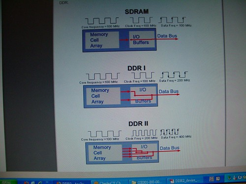
SDRAM, DDR, and DDRII 示意圖

這一篇 有很好的圖示,說明 SDRAM, DDR, DDRII 的 clock 差異

因為直接連圖不好意思,所以說明一下大概的原理:

假設 RAM Cell clock 都是 100MHz...
  • SDRAM 的 data 輸出和 data clock 的 rising edge 同步,所以也是 100MHz,因為一次一筆,所以不用 buffer 就直接輸出。
  • DDR 的 data 輸出和 data clock 的 rising edge, falling edge 都同步,所以一樣用 100MHz,但是因為一個edge 只能 output 一筆,所以內部要先 buffer 一份
  • DDR II 把輸出clock 增加一倍,而且也是 rising/falling edge 都輸出,所以內部要 buffer 3 份 data
... 這樣說起來有點奇怪,還是直接看圖好了..
IMGP1396
本來以為內部buffer 的 data 用來解釋 CL (data - to CMD delay) ,但是好像不是喔。
內部 buffer 只需要 delay 待會 才要的 data,第一筆 data 還是可以直接 output 出去,不需要 delay 的喔。

VFP in CE 6.0

有關 CE 6 的 ARM VFP 支援

這一篇 google groupe討論
The VS2005 compiler used by PB for CE6.0 emits no VFP instructions and
unless you implement FPCRT.DLL for an ARM then all CE implementations
are integer (default MS implementation of FPCRT uses software
emulation), even if you have a hardware VFP in your core (e.g. ARM11
or Cortex-A8). To actually use the VFP you must do the following:

1. Use SYSGEN_OEM_FPCRT - catalog item "OEM Floating Point CRT (ARM
only)
2. Download the VFPv2 library support from the ARM website and
incorporate it into your build:
www.arm.com/products/os/windowsce_vfp_dl.html

Instructions are included with the download from ARM.

My tests show a 4x increase in performance on floating point
operations on a release build on an ARM1136JF-S core.

Andrew.

也就是說,CE 6 的 VFP driver(?) library f是由 ARM 提供的。

還有這一篇 MSDN 討論,說
The current version of Windows CE supports the ARMV4I architecture. Cortex A8 it's ARMv7 (ARM's naming can be even more confusing than ms one...) and currently the compiler does not use its specific features (NEON, VFP3 etc.).

The new release of Windows CE (named Windows Embedded Compact 7) will support the ARMv7 architecture.

Here you can find some information about the new features of this release:

http://www.microsoft.com/windowsembedded/en-us/products/windowsce/compact7.mspx

You can download a public beta from connect.microsoft.com.

If your project has not a very short time frame (you plan to release your device Q2 next year, for example), you may consider using this new release for your development to be able to "unleash" all the power of your CPU core.


Valter Minute
Windows Embedded MVP
http://geekswithblogs.net/WindowsEmbeddedCookbook

所以你藥用 CE 6 寫 VFP 或是 NEON 的 code 是不可能的,要等 Windows Embedded 7.

總合起來,可以要看一下 msdn :
Including a Replacement Floating Point C Run-Time Library in a Run-Time Image
還有這一篇的實做 copy 下來,免得不見:

Download and install the "ARM® VFPv2 Floating Point Support Library" from ARM.


If building with Platform Builder to build your OS image

simply add the FPCRT project to your solution, and set the following catalog feature

EVM_3530\Core OS\CEBASE\Applications and Services Development\C Libraries and Runtimes\OEM Floating Point CRT (ARM only)

A SYSGEN is required.


If building without Platform Builder, ensure the SYSGEN variable is set. I added the following to my "tinykernel DEBUG.bat" file.

set SYSGEN_OEM_FPCRT=1

Add entries to platform.bib

fpcrt.dll            $(_FLATRELEASEDIR)\fpcrt.dll               NK  SH
k.fpcrt.dll $(_FLATRELEASEDIR)\fpcrt.dll NK SHMK

I copied the contents of %WINCEROOT%\OTHERS\ARM\VFPv2\src\ARMVFPv2\obj to my prebuilt directory.
Then copied the DLL project to my %WINCEROOT%\OTHERS\ARM\VFPv2\src\FPCRT to my %PLATFORMROOT%\%_TGTPLAT%\src\drivers directory.
Modified dirs, and updated sources to point to new library location.

A SYSGEN is required.

Visual Studio 2008 VFP Support

VS2008 ARM compiler supports emulated and hardware floating point. To enable hardware based Vector Floating point you need to use this option

/QRfpe-

This means not floating point emulation.

If you use

/QRfpe

it will generate software floating point, as it means floating point emulation.

Microsoft KB 947894


Note: This is not related to NEON support


有關 multimedia (video/audio/graphic) 部份,ARM 有提供 OpenMax 的實做 (實際用 ARM11, Cortex A8 feature optimize) 的 library
Khronos Standards
...但是依照慣例,ARM的網頁連結 半年後一定又會改 >_<

要註冊才能download..
喔?是以 library 的方式提供,用 realview compile (當然不是 VS...)
7.12.2010

取得 4 種 size/範圍 的 DC (Device Context)
  • BeginPaint(hwnd, &ps) : 這個範圍最小,只有視窗中,client 的 "invalide" 區域,可以畫。
  • GetDC(hwnd) : 整個 Client area (也就是不含 menu, toolbar, statusbar,...)
  • GetWindowDC(hwnd) : 整個視窗 (含 client area, menu, toolbar , statusbar..)
  • CreateDC("DISPLAY",NULL,NULL,NULL) : 整個螢幕

7.08.2010

Speed up Windows CE boot time

以第一個 application 畫面顯示出來為準...

首先是,,改用 XIP。
XIP 的話,NK 被切成 tiny 和 BINFS 兩部份, bootloader 只要load binfs 就可以開始啟動 os 了,不用把整個 OS bin 都 load 進來 才動作,所以可以比較快。

用 msdn 的 delay load driver - busenum2
一些不急的 driver 等 gwes , ap load 完後再load。這樣 就可以比較快進入 ap.

bootloader
直接 load os,不要 作 2 step loading -- load eboot, eboot load os。這樣可以比較快。


但是怎麼作,好像都要 8 sec 以上,要做出 5 sec 開機好像不可能喔...

bootloader load tinybin, binfs 啟動就花 3 sec
load gwes, gmtt_o 又花 1.6 sec 以上

再加一些其他啦里啦鉔的....

7.05.2010

再作 celog.dll - boot time

因為要作 msdn 那個 delay load driver 的測試,所以把 celog 也 enable 起來:

在 os project 勾選
  • enable event tracking during boot
  • flush tracked event to release directory
然後 修改 makexip.js,把 celog.dll 放到 boot region。


參考 http://msdn.microsoft.com/en-us/library/aa450700.aspx
設定

[HKEY_LOCAL_MACHINE\System\CeLog]
"Transport"="LocalFile"
"FileName"="\\celog.clg"
"ZoneCE"=dword:00014040
"FlushTimeout"=dword:1F4

log 到 ram, 每 500ms flush 到 ram file一次 (避免 data loss)
log 的東西:
  • CELZONE_BOOT_TIME 0x00010000 -- 包含 boot event
  • CELZONE_LOADER 0x00004000 -- 包含 load module (dll) 的 event
  • CELZONE_PROCESS 0x00000040 -- 包含 create process (exe) 的 event
重 build 開機後,就可以看到 celog.clg 在 // 下, copy 到 SD。
開啟 build environment:
 readlog celog.clg output.txt
把 clg 轉為文字。

就可以看到 load module 和 create process event 的時間了。

clone public code

大概就是用 sysgen_capture 這個 tool 來作:

首先找到 sysgen 的 targetname。假設是 celogflush 好了
* 在 platform/yourbspname 下 create 一個 folder : celogflush
* 在 celogflush 下: sysgen_capture -p common celogflush
* copy public/common/sdk/samples/celog/flush/celogflush/flush.c 過來
* 因為 celogflush/sources 有列 include path : ..,所以把 ../*.h 也 copy 過來
* rename 剛剛 sysgen_capture 產生的 sources.celogflush 為 sources
* 修改 sources,把 source = 加上 flush.c
* copy Makefile 過來
這樣就可以下 build,產生 celogflush.exe 了

主要大概是用 sysgen_caputre 產生 target 的 source 檔,這樣才知道 target 用的 library 有哪些。

把 source file copy 過來,修改 sources。
雖然 library 中會有同樣的 sample,但是大蓋會以 source = 列出的優先(吧?)