2.28.2008

CONTAINING_RECORD

PCHAR CONTAINING_RECORD(
PCHAR Address,
TYPE Type,
PCHAR Field
);
是一個MACRO,將 Structure 中某個field的offset 取出。
以上面的宣告來說,會 return : "Address" + "Filed" 在 strucure "Type" 中的offset。

這樣做的原因是為了避免 hard coding offset 在 source 中,造成 structure 內容變更不易。

這一篇 有說明 :


typedef struct _BUFFER {
LIST_ENTRY e;
UCHAR *buf;
} BUFFER, *PBUFFER;

...
PLIST_ENTRY entry = RemoveHeadList(&listHead);

PBUFFER a = CONTAINING_RECORD(entry, BUFFER, e);
為例, a 其實可以直接將 entry cast成 LIST_ENTRY就可以。

但是這樣以後 BUFFER 這個structure 若是修改的話,這樣寫就會有問題。
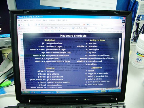
keyboard shortcut in Google Reader

原來 Google Reader 按下 "?" 就會出現 keyboard shortcut:

2.27.2008

MSN Direct

MSN Direct 是一個像TMC 的東西:RF receiver。

但是內容是數位的 (數位廣播?)。

廣播的內容可以有很多,像traffic condition, weather, ....

還有MS廣告中的,可以訂購的服務,做到 push personal information to smart device (黑莓機?).

目前已經有一堆 PND 內建這個功能了。

HalAllocateCommonBuffer

HalAllocateCommonBuffer

PVOID HalAllocateCommonBuffer(
PDMA_ADAPTER_OBJECT DmaAdapter,
ULONG Length,
PPHYSICAL_ADDRESS LogicalAddress,
BOOLEAN CacheEnabled
);

是要alloc一塊memory給 "不認識virtual address" 的hardware用 (?)

參數中指定需要的大小 (Length) 和 CacheEable。並且指定是要給哪一個hardware用 (DmaAdaptor)。
    pVirtDMABufferAddr =
(PBYTE)HalAllocateCommonBuffer(&Adapter,(AUDIO_DMA_PAGE_SIZE),&PhysDMABufferAddr, FALSE);
就會alloc一塊memory,memory的virtual address會return 回來,physical address 就放在 argument 的 "LogicalAddress" 中。

一般是給DMA用 (DMA只認識 physical address ?)

以 DMA 的 output channel 來看,allocate的memory,physical address要填入DMA的source pointer register。
DMA.SourceAddress = LogicalAddress。
然後,driver要藉由DMA送出資料,就要寫入 pVirtDMABufferAddr

4 Bit ECC algorithm

4 bit ECC 有兩種 algorithm :
  • Reed Solomon
  • BCH
S 公司的ECC好像是用後者。

MS Office file formate so complicated

Why are the Microsoft Office file formats so complicated? (And some workarounds)
錢一陣子MS公佈了Office的文件規格。

然後就有上面Joel 的這一篇文章。
滴滴麵 的blog中有中文說明喔。

其實資質駑頓的我在MS的環境中一直有這樣的疑問:為甚麼這裡要作得這麼複雜?XXX這樣作不就好了嗎?

看來,深奧的MS世界還真不是我可以瞭解的..

2.26.2008

todo

Loyal 已經確認busy thread 在 wave driver中,要查一下...

battery driver - notify and state change

battery driver竟然用兩個thread (不同步)

一個在 driver interface : init 時 create : Battery

BatteryThreadProc :
BatteryAPIGetSystemPowerStatusEx2(&tmpst);
IfPowerChange ( &tmpst, &pbc->st )
用來比較的另一個變數pbc->是
pbc = (PBATTERY_CONTEXT) pvParam;
pvParma 是ThreadProc的argument :
DWORD WINAPI   BatteryThreadProc(PVOID pvParam)
在createthread時:
ghtBattery = CreateThread(NULL, 0, BatteryThreadProc, &gBatteryContext, 0, NULL);
所以pbc 就是gBatteryContext。

這個variable好像在其他process中沒有人用,所以是給 BatteryThreadProc專用的。
所以 tempst 和pbc->st 的動作,是在 IfPowerChange( )中update的。

但是也不是每次call都update,分成
  • Only Voltage Change
  • Other Change
Only Voltage Change的話,不update battery new, old。

當IfPowerChange( ),就用 PowerPolicyNotify(PPN_POWERCHANGE, 0) 通知 Power Management driver。


ToDo : 如果voltage 還沒到 low voltage confirm, 要postmessage的電壓,但是 lifepercentage已經是 0 ,會不會 auto-off ?

結果: 不是kernel 關的,還是battery driver自己關的,在UpdateStatus( )這個Thread中有判斷batterypercentage 和 voltage,都達到 MIN value後,就會postmessage跟call keyboard event.

實際上送出 off message的只有一個地方 : updatestatus( )。

DAV_SVN : SVNAutoversioning

James說SVN在web folder為甚麼不能直接拖拉了?

Try了一下,真的不行,然後到 /var/log/apache2/error.log 看一下,message是:
No such file or directory : <DAV:cannot-modify-checked-in-parent>
Google一下,就有解答:
http://svn.haxx.se/users/archive-2007-03/0089.shtml
所以修改 /etc/apahce2/mod-available/dav_svn.conf加入 SVNAutoversioning on重新啟動apache2 後。

OK

2.25.2008

log - hang on splash screen

死掉的
....
OVL_LEFT 19
OVL_RIGHT 237
OVL_WIDTH 218
OVL_TOP 191
OVL_HEIGHT 30
OVL_BOTTOM 221
BAR_COLOR_BORDER=0x2945
BAR_COLOR_BASE=0x4A49
BAR_COLOR_ACTIVE=0x3F7E
OEMIoControl: Unsupported Code 0x10100fc - device 0x0101 func 63
Ps2Keybd::Initialize
Ps2Keybd::Initialize Done
IsrThreadStart:
++KeybdDriverInitializeAddresses
HARDWARE\DEVICEMAP\KEYBD\IOBase:b2100000
HARDWARE\DEVICEMAP\KEYBD\SSPBase:b1d00000
[KBD] v_pIOPregs mapped at 150000
Ps2KeybdIsrThread:
--KeybdDriverInitializeAddresses
IsrThreadProc:
Lyg.p: Layout Manager successfully initialized to 2
Maximum Allowed Error 7:
StreamContext::GainChange
-Codec_channel
Ufnpdd_ISTMain
SDE
HFSUSP
HFRM
USB Attached
HFRES

正常的...
OVL_RIGHT 237
OVL_WIDTH 218
OVL_TOP 191
OVL_HEIGHT 30
OVL_BOTTOM 221
BAR_COLOR_BORDER=0x2945
BAR_COLOR_BASE=0x4A49
BAR_COLOR_ACTIVE=0x3F7E
OEMIoControl: Unsupported Code 0x10100fc - device 0x0101 func 63
Ps2Keybd::Initialize
Ps2Keybd::Initialize Done
IsrThreadStart:
++KeybdDriverInitializeAddresses
HARDWARE\DEVICEMAP\KEYBD\IOBase:b2100000
HARDWARE\DEVICEMAP\KEYBD\SSPBase:b1d00000
[KBD] v_pIOPregs mapped at 150000
--KeybdDriverInitializeAddresses
Ps2KeybdIsrThread:
Lyg.p: Layout Manager successfully initialized to 2
IsrThreadProc:
Maximum Allowed Error 7:
StreamContext::GainChange
-Codec_channel
MSIM: IM_ReadRegistry read KB 5
-Codec_channel
+OEMSetAlarmTime(3/9/2008 2:0:0.000)

PWR_IST: pPWR->State = 0x2
PWR_IST back
Ufnpdd_ISTMain
HFSUSP
HFRM
USB Attached
StreamContext::GainChange
-Codec_channel
+OEMSetAlarmTime(3/9/2008 2:0:0.000)
-Codec_channel
+OEMSetAlarmTime(3/9/2008 2:0:0.000)
DeviceConext::SetGain 99999999
+OEMSetAlarmTime(3/9/2008 2:0:0.000)
狀態:SD card in, usb 接adptor.
第二次,使用boot message shell..
fail 的log
BAR_COLOR_BORDER=0x0
BAR_COLOR_BASE=0x3A07
BAR_COLOR_ACTIVE=0x7E0
OEMIoControl: Unsupported Code 0x10100fc - device 0x0101 func 63
BatteryVoltage 4153 4164
BatteryThreadProc PowerPolicyNotify(PPN_POWERCHANGE, 0)
Ps2Keybd::Initialize
Ps2Keybd::Initialize Done
IsrThreadStart:
++KeybdDriverInitializeAddresses
HARDWARE\DEVICEMAP\KEYBD\IOBase:b2100000
HARDWARE\DEVICEMAP\KEYBD\SSPBase:b1d00000
[KBD] v_pIOPregs mapped at 150000
--KeybdDriverInitializeAddresses
Lyg.p: Layout Manager successfully initialized to 2
Maximum Allowed Error 7:
Ps2KeybdIsrThread:
IsrThreadProc:
StreamContext::GainChange
-Codec_channel
Ufnpdd_ISTMain
HFSUSP
HFRM
成功的會是.
BAR_COLOR_BORDER=0x0
BAR_COLOR_BASE=0x3A07
BAR_COLOR_ACTIVE=0x7E0
OEMIoControl: Unsupported Code 0x10100fc - device 0x0101 func 63
Ps2Keybd::Initialize
Ps2Keybd::Initialize Done
IsrThreadStart:
++KeybdDriverInitializeAddresses
HARDWARE\DEVICEMAP\KEYBD\IOBase:b2100000
HARDWARE\DEVICEMAP\KEYBD\SSPBase:b1d00000
[KBD] v_pIOPregs mapped at 150000
--KeybdDriverInitializeAddresses
Lyg.p: Layout Manager successfully initialized to 2
Maximum Allowed Error 7:
Ps2KeybdIsrThread:
IsrThreadProc:
StreamContext::GainChange
-Codec_channel
MSIM: IM_ReadRegistry read KB 5
-Codec_channel
+OEMSetAlarmTime(3/9/2008 2:0:0.000)
>> PnaShell is launched up........!

PWR_IST: pPWR->State = 0x2
PWR_IST back
BatteryVoltage 4164 4153
BatteryThreadProc PowerPolicyNotify(PPN_POWERCHANGE, 0)
BatteryVoltage 4142 4164
BatteryThreadProc PowerPolicyNotify(PPN_POWERCHANGE, 0)
BatteryVoltage 4153 4142
BatteryThreadProc PowerPolicyNotify(PPN_POWERCHANGE, 0)
Ufnpdd_ISTMain
HFSUSP
HFRM
StreamContext::GainChange
-Codec_channel
+OEMSetAlarmTime(3/9/2008 2:0:0.000)
-Codec_channel
+OEMSetAlarmTime(3/9/2008 2:0:0.000)
BL_On(TRUE)
>>> ++HWSetBacklightDutyCycle percentage:: 55
>>> TIMER_CNT = 5050
>>> --HWSetBacklightDutyCycle
BL_On: Turning AC backlight ON
BL_MonitorThread Registry event
+OEMSetAlarmTime(3/9/2008 2:0:0.000)
DeviceConext::SetGain 99999999
+OEMSetAlarmTime(3/9/2008 2:0:0.000)
BL_On(TRUE)
BL_MonitorThread Registry event
+OEMSetAlarmTime(3/9/2008 2:0:0.000)
BatteryVoltage 4164 4153
BatteryThreadProc PowerPolicyNotify(PPN_POWERCHANGE, 0)
BatteryVoltage 4153 4164
BatteryThreadProc PowerPolicyNotify(PPN_POWERCHANGE, 0)
BatteryVoltage 4164 4153
BatteryThreadProc PowerPolicyNotify(PPN_POWERCHANGE, 0)
BatteryVoltage 4153 4164
BatteryThreadProc PowerPolicyNotify(PPN_POWERCHANGE, 0)
BatteryVoltage 4164 4153

2.22.2008

沒做完的事

  1. battery voltage要重新校正
  2. FM發射器新增功率設定
  3. 新LCD driver
  4. Pwr button 有點怪怪的

好奇怪,我的機器build出來的wake up 會出現usb-in message(nathan說得,因為messasge不完整)。
但是相同都是從VSS checkout的code,在building machine上卻不會....

  1. 要試試是從哪一個rev (from svn)上開始有這個問題的 (build時要確認 usbms 有define)
  2. 要試試disable debug message會不會發生
  3. 猜測是 sd in out message,print out number 看看 (correct and error bin)

有關 postmessage error 問題:

重新sysgen 後就OK了。

sysgen 的注意事項:
  • sysgen 不會重新build bsp (要用sysgen and build current BSP 才會)
  • public folder 內有修改的東西,sysgen 不會自動重build,要自己手動去build (e.g : usbmsfn)

wakeup後會跳出usb in message的原因是:
以前的usb-in/out message post實做在 public 的usbfn bot.cpp中,但是新的實做在 driver ufnpdd 中,但是在public fusbfn 的bot.cpp 的postmessage code沒有刪掉,所以造成這樣。

Killer AP for PND (?)

今天看到的新產品新聞 (link忘了)

原來

GPS 車機最好的附加功能 (Killer AP)是.... 酒精濃度偵測 裝置。


會不會變成標準配備 ?

James提醒:會有客訴吧...
為甚麼GPS說我酒精濃度可以開車,但是警察的酒測卻沒過?

2.21.2008

MAX9850 Register : 0x05 ENABLE

0x05 (Enable Register)內含各function的enable bit:
  • bit 7 : ~ SHDN : shutdown 整個codec
  • bit 6 : MCLKEN : DAC需要外部MCLK,但是 LineIn/Out 和Headphone部份則不需要
  • bit 5.4 : CPEN : Charge Pump Enable : 讓LineOut , Headphone的Charge Pump功能enable起來
  • bit 3 : HPEN : Enable Headphone output (有一句 "The Line Output must be enabled for the headphone amplifiers to operate properly",是說 enable headphone時,lineout也要enable才行嗎?)
  • bit 2 : LNOEN : Enable LineOut (回應上一個問題:Yes)
  • bit 1 : LNIEN : Enable LineIn
  • bit 0 : DAC : Enable DAC.
所以比較要注意的就是headphone和Lineout之間的關係,headphone依賴Lineout。
所以如果有人設計 Lineout 直接以固定AMP gain 推speaker,則插入headphone時,speaker無法關閉。

這也就表示 MAX9850不支援Lineout直接接speaker (所以lineout沒有獨立gain control ?)。

所以LNOEN 一值要是1就是了

程式設計上,雖然用read-modify-write比較好(減少相依)。但是由於read-write之間形成一個critical section,然後I2C I/O部份又是一個critical section。

CE的critical section又有點像 mutex,不是完全的disable context switch,所以這樣作有機會會造成dead-lock (還有內建priority-inversion?)

所以有點危險。只好每一個function用一個variable來代表狀態,每次write時依照variable重新算出數值。

需要的variable有
  • headphonein
  • lineinopen
其他的部份:LNOEN一直要是enable。 lineinopen的話,DAC就要disable。

2.20.2008

log IIC - max9850 - traditional code.


DoI2CIO: SET_READ_ADDR
Drop: 0x21
DataCount: 0x0
ACK NOT received
RECEIVED DATA1:: 0x4
DoI2CIO: SET_READ_ADDR
Drop: 0x21
DataCount: 0x0
ACK NOT received
RECEIVED DATA1:: 0x4
StreamContext::GainChange
DoI2CIO: SET_READ_ADDR
Drop: 0x21
DataCount: 0x0
ACK NOT received
RECEIVED DATA1:: 0xC
DoI2CIO: SET_READ_ADDR
Drop: 0x21
DataCount: 0x0
ACK NOT received
RECEIVED DATA1:: 0x4
DoI2CIO: SET_READ_ADDR
Drop: 0x21
DataCount: 0x0
ACK NOT received
RECEIVED DATA1:: 0x4
DoI2CIO: SET_READ_ADDR
Drop: 0x21
DataCount: 0x0
ACK NOT received
RECEIVED DATA1:: 0x4
DoI2CIO: SET_READ_ADDR
Drop: 0x21
DataCount: 0x0
ACK NOT received
RECEIVED DATA1:: 0x4
DoI2CIO: SET_READ_ADDR
Drop: 0x21
DataCount: 0x0
ACK NOT received
RECEIVED DATA1:: 0x4

Workrecord.

實在太亂了...紀錄一下 rev.
1012 : 加上 debug log。
回到986,用原來的driver,加上debug message,check IIC pin configuration。
986 有問題,shell 進入後 touch panel 失效,
改到 987 : 一樣。
==> 結果是release folder platform.bib comment掉wave driver,導致 camera 的 i2c hang 住 (?)。
加入 print,camera driver的GPECON a44552aa GPEUDP FF3FFFFF
所以 GPE 14 (IICSCL), 15(IICSDA) 都是 disabled (11b).
回到 1012 : 將GPEUDP 設為disable,結果一樣是no ACK.
1015:把wave driver也改成用I2C, write 似乎OK,read 還是 poll error - no ACK.
1016 : 加一堆 debug message 在 IIC core中。
回到 986 - 一樣在core中加debug message。
發現...log (ref next post),竟然一樣..read operation ends with "ACK NOT received".
commite : 1017
回到1016.

IIC 的動作就是..
  • 把data放到IICDS
  • clear 掉 ack pending bit (IICCON)
  • controller 開始傳送
  • controller 收到 ack後 set ack pending bit
  • 回到第一步,傳送下一個byte

2.15.2008

莫聽穿林打葉聲,何妨吟嘯且徐行。

竹杖芒鞋輕勝馬,誰怕? 一蓑煙雨任平生。
料峭春風吹酒醒,微冷, 山頭斜照卻相迎。
回首向來蕭瑟處,歸去, 也無風雨也無晴。

2.14.2008

利用眼睛虹膜作為相片版權印記

Canon 新的專利:利用眼睛虹膜作為相片版權印記

大概是說相機有一個功能是由viewfinder拍攝 攝影者個虹膜,然後內嵌到鎖拍攝的相片中。

這樣,以後就可以利用相片中的虹膜來辨識出拍攝者。

這倒是蠻直覺的,因為大部分的DSLR還是用ViewFinder而不是用LCD取景。

2.12.2008

問題:
  1. Power Button 有時候沒動作 (when ? after software reset ? 還有其他的 ?)
  2. 太多的message會導致 system freeze.

2.05.2008

Lcd Panel power up sequence

感激Eric與Franz的說明

LCD panel 與MCU的interface一般包含
  1. Panel power
  2. Panel reset
  3. lcd data/clock bus
  4. spi/i2c (option)
其中 spi/i2c bus是為了config panel 的參數,在該panel 產量大時,就不需要了 (pre-program在 panel mcu中)。

以上各部份的power sequence 一般會是..
  1. panel power 打開
  2. 產生panel reset 信號,讓panel mcu reset
  3. 使用spi/i2c program panel mcu 參數
  4. enable lcd data/clock bus
* 在 enable lcd data/clock bus signal 之前,要讓lcd bus維持在 floating mode。以免影響 panel 內mcu的同步。

每個動作要注意 power settle time,要delay。還有 panel reset後,要給panel mcu initialize 的時間,所以也要delay。

有些panel 在一開始送出lcd bus data時,要先送出 all white data。N frame後才可以開始真正的動作。

*有些panel 有提供 PON (panel ON) pin。這是在所有動作 (1,2,3,4)都做完後,最後才動作的pin。意思是告訴 panel : everthing OK, ready to GO!

2.04.2008

MS 要收購 Yahoo,第一個想到的是..

那...以後 Yahoo 的平台都要改 IIS + MS SQL + .NET ?